Placing code and data—the linker configuration file
The placement of sections in memory is performed by the IAR ILINK Linker. It uses the linker configuration file where you can define how ILINK should treat each section and how they should be placed into the available memories.
A typical linker configuration file contains definitions of:
Available addressable memories
Populated regions of those memories
How to treat input sections
Created sections
How to place sections into the available regions
The file consists of a sequence of declarative directives. This means that the linking process will be governed by all directives at the same time.
To use the same source code with different derivatives, just rebuild the code with the appropriate configuration file.
A simple example of a configuration file
Assume a simple 32-bit architecture that has these memory prerequisites:
There are 4 Gbytes of addressable memory.
There is ROM memory in the address range
0x0000–0x10000.There is RAM memory in the range
0x20000–0x30000.The stack has an alignment of 16.
The system startup code must be located at a fixed address.
Note: The following examples of linker configuration files are generic assumptions or theoretical examples that show how different directives work for ILINK.
A simple configuration file for this assumed architecture can look like this:
/* The memory space denoting the maximum possible amount
   of addressable memory */
define memory Mem with size = 4G;

/* Memory regions in an address space */
define region ROM = Mem:[from 0x00000 size 0x10000];
define region RAM = Mem:[from 0x20000 size 0x10000];

/* Create a stack */
define block STACK with size = 0x1000, alignment = 16 { };

/* Handle initialization */
initialize by copy { readwrite }; /* Initialize RW sections */

/* Place startup code at a fixed address */
place at start of ROM { readonly section .cstartup };

/* Place code and data */
place in ROM { readonly }; /* Place constants and initializers in
                              ROM: .rodata and .data_init    */
place in RAM { readwrite,  /* Place .data, .bss, and .noinit */
               block STACK }; /* and STACK                   */
This configuration file defines one addressable memory Mem with the maximum of 4 Gbytes of memory. Furthermore, it defines a ROM region and a RAM region in Mem, namely ROM and RAM. Each region has the size of 64 Kbytes.
The file then creates an empty block called STACK with a size of 4 Kbytes in which the application stack will reside. To create a block is the basic method which you can use to get detailed control of placement, size, etc. It can be used for grouping sections, but also as in this example, to specify the size and placement of an area of memory.
Next, the file defines how to handle the initialization of variables, read/write type (readwrite) sections. In this example, the initializers are placed in ROM and copied at startup of the application to the RAM area. By default, ILINK may compress the initializers if this appears to be advantageous.
The last part of the configuration file handles the actual placement of all the sections into the available regions. First, the startup code—defined to reside in the read-only (readonly) section.cstartup—is placed at the start of the ROM region, that is at address 0x10000.
Note: The part within {} is referred to as section selection and it selects the sections for which the directive should be applied to. Then the rest of the read-only sections are placed in the ROM region.
Note: The section selection { readonly section .cstartup } takes precedence over the more generic section selection { readonly }.
Finally, the read/write (readwrite) sections and the STACK block are placed in the RAM region.
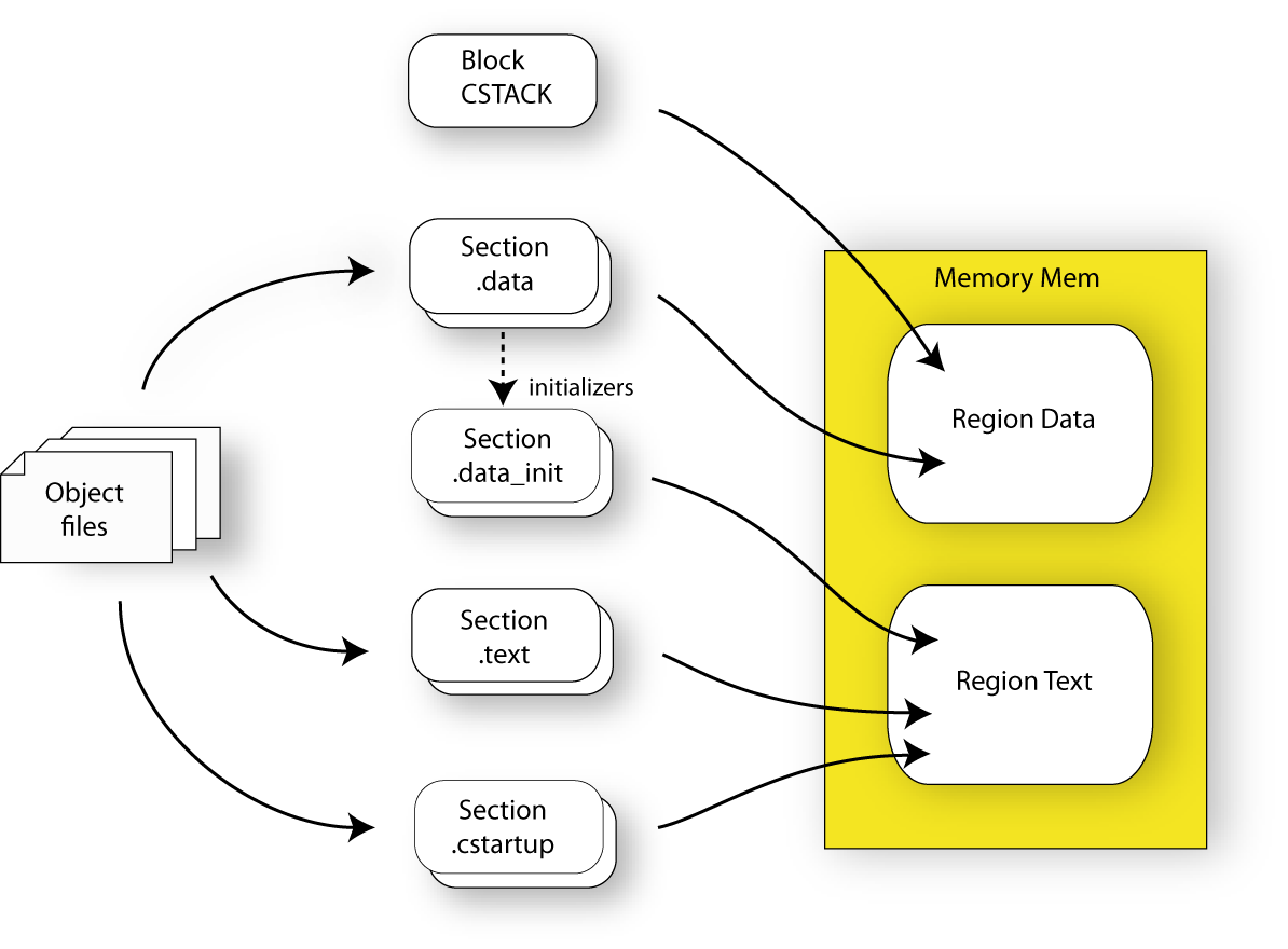
This illustration gives a schematic overview of how the application is placed in memory:
In addition to these standard directives, a configuration file can contain directives that define how to:
Map a memory that can be addressed in multiple ways
Handle conditional directives
Create symbols with values that can be used in the application
More in detail, select the sections a directive should be applied to
More in detail, initialize code and data.
For more details and examples about customizing the linker configuration file, see Placing code and data—the linker configuration file.
For more information about the linker configuration file, see Overview of the linker configuration file.