- IAR Embedded Workbench for RX 5.20
- C-SPY Debugging
- Getting started using C-SPY
- Reference information on starting C-SPY
- Hardware Setup dialog box: MCU
Hardware Setup dialog box: MCU
The Hardware Setup dialog box for the hardware debuggers is available from the C-SPY driver menu. Before C-SPY is started for the first time in a new project, and when you change devices, the hardware must be configured.
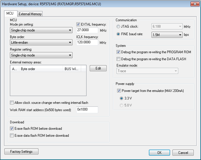
Use the MCU options page to make general settings that control how the emulator operates.
Requirements
A C-SPY hardware debugger driver.
Mode pin setting
Controls the MCU operation based on the pin settings. Choose between:
Single-chip mode
User boot mode
USB boot mode.
Note
Not all modes are available for all devices or all hardware debuggers.
EXTAL frequency
Specify the frequency in MHz of the external clock source that supplies the target MCU.
ICLK frequency
Specify the frequency in MHz of the internal clock source.
Note
This option is not available for all devices or all hardware debuggers.
Byte order
Controls the byte order of the device. Choose between:
Little-endian
Big-endian.
Note
This option is not available for all devices or all hardware debuggers.
Register setting
Controls the MCU operation based on register settings. Choose between:
Single-chip mode
On-chip ROM enabled extended mode
On-chip ROM disabled extended mode.
Note
Not all modes are available for all devices or all hardware debuggers.
External memory areas
Lists the defined external memory areas. To edit a memory area, select the area and click Edit to display the External Area dialog box, see External Area dialog box.
- Area
The name of the external memory area.
- Byte order
Identifies whether the byte order is the same as the byte order of the MCU or different.
- BUS width
The bus width of the area: 8, 16 or 32 bits.
No external memory areas are defined if the Register setting is Single-chip mode.
Allow clock source change when writing internal flash
Allows the clock source to change while internal flash memory is being rewritten in the emulator.
Work RAM start address
Specify the start address of the working RAM area for the debugger. The specified amount of bytes, beginning with the start address you specify, is used by the emulator firmware. The debugger uses the memory area when programming the on-chip flash memory, so the working RAM must be within the on-chip RAM area.
Your application can also use this area (because memory data in this area will be saved on the host computer and then restored), but do not specify any address in this area as the origin or destination of a transfer by the DMA or DTC.
Erase flash ROM before download
Erases the (internal) flash ROM before your application is downloaded. If this option is deselected, the flash ROM memory will not be erased by the downloading process. This means that any addresses that are not overwritten by the downloaded image will keep their previous contents.
Note
If multiple images are downloaded, you must deselect this option.
Erase data flash ROM before download
Erases the (internal) data flash ROM before your application is downloaded. If this option is deselected, the data flash ROM memory will not be erased by the downloading process. This means that any addresses that are not overwritten by the downloaded image will keep their previous contents.
Communication
Controls the communication between the emulator and the host computer. Choose between:
- JTAG clock
Selects the JTAG interface. Choose a communication clock frequency.
- FINE baud rate
Selects the FINE single wire debug interface. Choose a communication speed in bits/second.
Note that this option is not available for all devices or all hardware debuggers.
Debug the program re-writing the PROGRAM ROM
Debugs the program which writes to the program ROM (flash memory).
Debug the program re-writing the DATA FLASH
Debugs the program which writes to the data flash memory.
Emulator mode
Controls how the hardware debugger can be used.
- Trace
Makes the trace functionality of the C-SPY driver available, see Collecting and using trace data.
Power target from the emulator
Select this option and the correct voltage if you are supplying the target board with power from the hardware debugger, and not from an external power supply.
If you select this option but connect an external power supply to the target board, the external power supply will be used instead and these settings will be ignored.
Note
This option is not available for all devices or all hardware debuggers.