J-Link/J-Trace — Connection
The Connection options specify the connection with the J-Link/J-Trace probe.
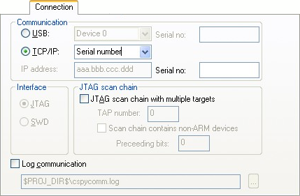
Communication
Selects the communication channel between C-SPY and the J-Link debug probe. Choose between:
- USB
Selects the USB connection. If Serial number is selected in the drop-down list, the J-Link debug probe with the specified serial number is chosen.
- TCP/IP
Specify the IP address of a J-Link server. The TCP/IP connection is used for connecting to a J-Link server running on a remote computer.
IP address, specify the IP address of a J-Link probe connected to LAN.
Auto detect, automatically scans the network for J-Link probes. Use the dialog box to choose among the detected J-Link probes.
Serial number, connects to the J-Link probe on the network with the serial number that you specify.
Interface
Selects the communication interface between the J-Link debug probe and the target system. Choose between:
- JTAG (default)
Uses the JTAG interface.
- SWD
Uses fewer pins than JTAG. Select SWD if you want to use the serial-wire output (SWO) communication channel. Note that if you select stdout/stderr via SWO on the General Options>Library Configuration page, SWD is selected automatically. For more information about SWO settings, see SWO Trace Window Settings dialog box.
JTAG scan chain
Specifies the JTAG scan chain. Choose between:
- JTAG scan chain with multiple targets
Specifies that there is more than one device on the JTAG scan chain.
- TAP number
Specify the TAP (Test Access Port) position of the device you want to connect to. The TAP numbers start from zero.
- Scan chain contains non-Arm devices
Enables JTAG scan chains that mix Arm devices with other devices like, for example, FPGA.
- Preceeding bits
Specify the number of IR bits before the Arm device to be debugged.
Log communication
Logs the communication between C-SPY and the target system to a file. To interpret the result, detailed knowledge of the interface is required.