J-Link/J-Trace — Setup
The Setup options specify the J-Link/J-Trace probe.
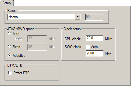
Reset
Selects the reset strategy to be used when the debugger starts. Note that Cortex-M uses a different set of strategies than other devices. The actual reset strategy type number is specified for each available choice. Choose between:
- Normal (0, default)
This is the default strategy. It does whatever is the best way to reset the target device, which for most devices is the same as the reset strategy Core and peripherals (8). Some special handling might be needed for certain devices, for example devices which have a ROM bootloader that needs to run after reset and before your application is started.
- Core (1)
Resets the core via the
VECTRESETbit—the peripheral units are not affected.
- Core and peripherals (8)
Resets the core and the peripherals.
- Reset Pin (2)
J-Link pulls its
RESETpin low to reset the core and the peripheral units. Normally, this causes the CPURESETpin of the target device to go low as well, which results in a reset of both the CPU and the peripheral units.
- Connect during reset (3)
J-Link connects to the target while keeping Reset active (reset is pulled low and remains low while connecting to the target). This is the recommended reset strategy for STM32 devices. This strategy is only available for STM32 devices.
- Halt after bootloader (4 or 7)
NXP Cortex-M0 devices. This is the same strategy as the Normal strategy, but the target is halted when the bootloader has finished executing. This is the recommended reset strategy for LPC11xx and LPC13xx devices.
Analog Devices Cortex-M3 devices (7), Resets the core and peripheral units by setting the
SYSRESETREQbit in the AIRCR. The core is allowed to perform the ADI kernel (which enables the debug interface) but the core is halted before the first instruction after the kernel is executed to guarantee that no user application code is performed after reset.
- Halt before bootloader (5)
This is the same strategy as the Normal strategy, but the target is halted before the bootloader has started executing. This strategy is normally not used, except in situations where the bootloader needs to be debugged. This strategy is only available for LPC11xx and LPC13xx devices.
- Normal, disable watchdog (6, 9, or 10)
First performs a Normal reset, to reset the core and peripheral units and halt the CPU immediately after reset. After the CPU is halted, the watchdog is disabled, because the watchdog is by default running after reset. If the target application does not feed the watchdog, J-Link loses connection to the device because it is permanently reset. This strategy is available for Freescale Kinetis devices (6), for NXP LPC 1200 devices (9), and for Samsung S3FN60D devices (10).
All of these strategies are available for both the JTAG and the SWD interface, and all strategies halt the CPU after the reset.
For other cores, choose between these strategies:
- Hardware, halt after delay (ms) (0)
Specify the delay between the hardware reset and the halt of the processor. This is used for making sure that the chip is in a fully operational state when C-SPY starts to access it. By default, the delay is set to zero to halt the processor as quickly as possible.
This is a hardware reset.
- Hardware, halt using Breakpoint (1)
After reset, J-Link continuously tries to halt the CPU using a breakpoint. Typically, this halts the CPU shortly after reset—in most systems, the CPU can execute some instructions before it is halted.
This is a hardware reset.
- Hardware, halt at 0 (4)
Halts the processor by placing a breakpoint at the address zero. Note that this is not supported by all Arm microcontrollers.
This is a hardware reset.
- Hardware, halt using DBGRQ (5)
After reset, J-Link continuously tries to halt the CPU using DBGRQ. Typically, this halts the CPU shortly after reset—in most systems, the CPU can execute some instructions before it is halted.
This is a hardware reset.
- Software (-)
Sets
PCto the program entry address.This is a software reset.
- Software, Analog devices (2)
Uses a reset sequence specific for the Analog Devices ADuC7xxx family. This strategy is only available if you have selected such a device from the Device drop-down list on the General Options>Target page.
This is a software reset.
- Hardware, NXP LPC (9)
This strategy is only available if you have selected such a device from the Device drop-down list on the General Options>Target page.
This is a hardware reset specific to NXP LPC devices.
- Hardware, Atmel AT91SAM7 (8)
This strategy is only available if you have selected such a device from the Device drop-down list on the General Options>Target page.
This is a hardware reset specific for the Atmel AT91SAM7 family.
For more information about different reset strategies, see the J-Link/J-Trace documentation available at www.segger.com .
A software reset of the target does not change the settings of the target system—it only resets the program counter and the mode register CPSR to its reset state. Normally, a C-SPY reset is a software reset only. If you use the Hardware reset option, C-SPY will generate an initial hardware reset when the debugger is started. This is performed once before download, and if the option Use flash loader(s) is selected, also once after flash download, see Debugging code in flash, and Debugging code in RAM.
Tip
Hardware resets can be a problem if the low-level setup of your application is not complete. If the low-level setup does not set up memory configuration and clocks, the application will not work after a hardware reset. To handle this in C-SPY, the setup macro function execUserReset() is suitable.For a similar example where execUserPreload() is used, see Remapping memory.
JTAG/SWD speed
Specify the JTAG communication speed in kHz. Choose between:
- Auto
Automatically uses the highest possible frequency for reliable operation. The initial speed is the fixed frequency used until the highest possible frequency is found. The default initial frequency—1000 kHz—can normally be used, but in cases where it is necessary to halt the CPU after the initial reset, in as short time as possible, the initial frequency should be increased. If the CPU starts at a low clock speed, you might need to set a lower initial value, for example 32 kHz.
A high initial speed is necessary, for example, when the CPU starts to execute unwanted instructions—for example power down instructions—from flash or RAM after a reset. A high initial speed would in such cases ensure that the debugger can quickly halt the CPU after the reset.
The initial value must be in the range 1–50000 kHz.
- Adaptive
Synchronizes the clock to the processor clock outside the core. Works only with Arm devices that have the
RTCKJTAG signal available. For information about adaptive speed, see the J-Link/J-Trace documentation available at www.segger.com .
Clock setup
Specifies the CPU clock. Choose between:
- CPU clock
Specifies the exact clock frequency used by the internal processor clock,
HCLK, in MHz. The value can have decimals. This value is used for configuring the SWO communication speed and for calculating timestamps.
- SWO clock
Specifies the clock frequency of the SWO communication channel in kHz.
- Auto
Automatically uses the highest possible frequency that the debug probe can handle. If Auto is not selected, the wanted SWO clock value can be input in the text box. The value can have decimals. Use this option if data packets are lost during transmission.
To override the Clock setup options, use the Override project default option in the SWO Configuration dialog box, see SWO Configuration dialog box.